- 4 Aktuální žádosti o pomoc Poraďte svým kolegům
- Požádejte o pomoc
- Podejte dotaz do fóra
- Vložit hotový případ
- LOG Decoder
Žádost o pomoc
Žádost o pomoc vyplňte, pokud máte rozpracovaný diagnostický případ na konkrétním vozidle, u kterého potřebujete pomoci zjistit skutečnou příčinu závady.
Pro naše nekonvenční metody je nutný základ znalostí a mít vlastní vybavení minimálně pro "logování", lépe však osciloskop. Nejlepší přípravou pro práci jsou naše videoškolení a akademie.
Jak to funguje?
Do online formuláře v jednotlivých krocích vyplníte všechny důležité údaje k případu a poté Vám ostatní registrovaní diagnostici poradí v komentářích*.
Supervizor a moderátoři FCD.eu samozřejmě vše doplňují a kontrolují správnost informací, aby cesta vedla ke správnému cíli.
Požádat o pomocDiagnostický případ
Z4 - Intermittent illumination of MIL light and long cranking
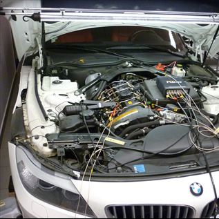
Informace o vozidle
| VIN: | WBALM71070E162880 |
| Výrobce: | BMW |
| Model: | Z4 |
| Rok výroby: | 2009 |
| Kód motoru: | 3,0 sDrive35i |
| Typ motoru: | N54 B30A |
| Výkon (kW): | 225 kW |
| Převodovka: | Automatická |
| Palivo: | Benzín |
| Najeto: | 49 132 km |
- během jízdy
- [29CC] Misfirings, several cylinders
- [29CF] Misfirings, cylinder 3
- [29D0] Misfirings, cylinder 4
- [29D9] Misfirings in case of tank filling level too low
- [29DB] Smooth running, Segment time measurement
- [29DC] Cylinder injection switch-off
- [2FBF] Fuel pressure at injection release
- trvalá závada
- sporadická závada
Doposud provedeno bez úspěchu
Nothing. The customer was sent to me by an authorised BMW workshop as they said due to the fact that the fault is intermittent locating the cause of the fault by them wouldn't be very effective.Závěr
VOZIDLO JSEM NEOPRAVOVALTwo different DTCs were discovered on the vehicle and they were not related to each other:
1. = High pressure pump is intermittently supplying low amounts of fuel (fuel injectors blocked during cranking) where replacement is necessary. This is not caused by insufficient fuel in the low pressure side circuit.
2. = Warm engine during load intermittently jerks in the area of 75-82% load. Found strongly contaminated intake ports and valve stems in the intake ports. We recommend to decarbonize the engine.
After high pressure pump replacement it will be necessary to verify if the cylinder misfire symptom at 78 - 82% engine load has been eliminated.
It is interesting that one of the DTCs is mentioning low fuel pressure despite the fact that the vehicle doesn't have a fuel low pressure sensor in the position indicated by the documentation.
Obrázky, fotografie a soubory
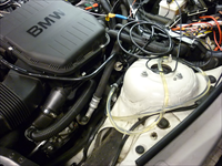
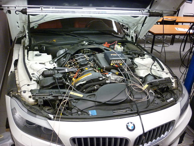
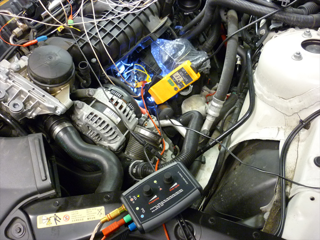
Connected to important signals (7107/1)
- Cylinder #2 - connected to positive and negative circuit of the piezo injector- Cylinder #2 - connected to the ignition module
- Connected to both wideband oxygen sensors
- Connected to the MAP sesnor
- Connected to the high pressure fuel sensor
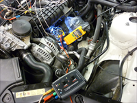
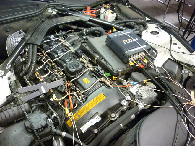
Connected to important signals 2 (7107/2)
- Cylinder #2 - connected to positive and negative circuit of the piezo injector- Cylinder #2 - connected to the ignition module
- Connected to both wideband oxygen sensors
- Connected to the MAP sesnor
- Connected to the high pressure fuel sensor
Symptom appears only while driving (7107/3)
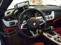
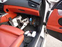
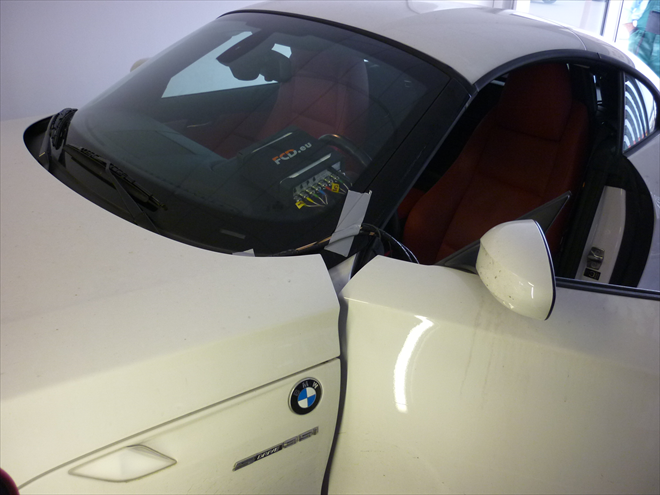
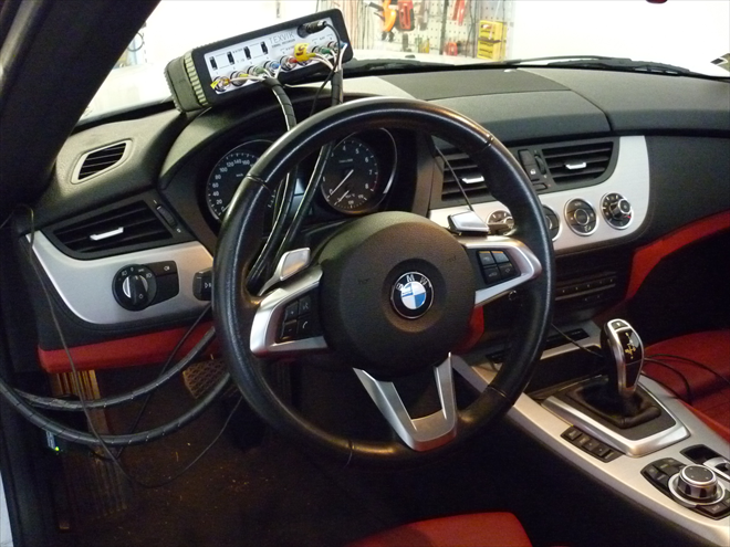
All 6 attempts to reproduce the problem in the workshop were unsuccessful. The Texvik was setup inside the vehicle to perform a test drive.Also Bavarian Technic diagnostic software specific for BMW vehicles was connected to the OBD connector.
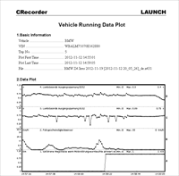
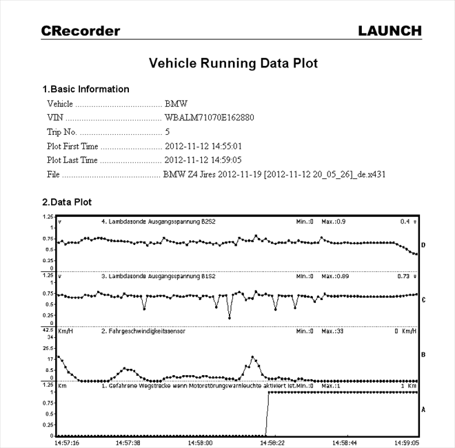
First test drives were done by the customer with an installed Launch CRecorder II data logger (7107/4)
CRecorder II recorded the fault during customers driving. On cylinder bank 1 we can see oxygen drops on the oxygen sensor behind the catalytic converter and immeadiately after that a DTC was set. The bottom most window where the trace in the second half changed from "0" to "1".Analysis of load zones (7107/5)
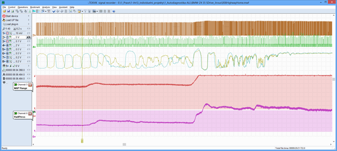
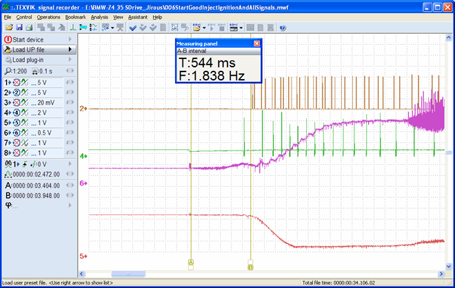
Channel designation:Ch2 - Brown = cylinder #2 injector
Ch4 - Green = cylinder #2 ignition
Thin brown - = Bank 1 Lambda sensor
Thin green = Bank 2 Lambda sensor
Ch5 - Red = MAP sensor
Ch6 - Pzrple = Rail high fuel pressure
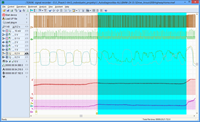
Recording: Test drive with 3 different engine loads.
Purpose: If the engine has misfires it is good to determine at what load they occur and at what loads they don't occur.
Analysis: At about 75% load there is no misfire and misfire begins at loads around 80% - 85%. At full load misfires continue for a short while but then they disappear.
Reasoning: At first sight there is no rail fuel pressure drop. (The fuel quantities are determined by a combination of pressures and time of one or more fuel injectors during one operating stroke.) It is not possible to clearly identify if the pressure reaches the expected value.
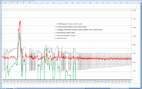
Test drive log recording (BavarianTechnic) (7107/6)
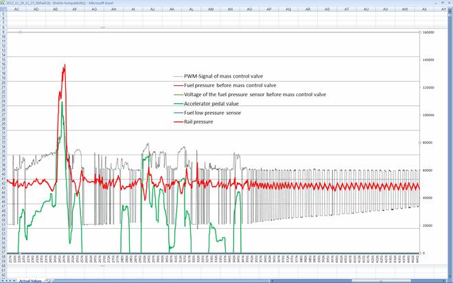
Recording descriptionCity test drive recording is showing that the high pressure regulator (red) is responding in line with the accelerator pedal (green), but it is not clear if this value corresponds with the expected pressure because the diagnostic software doesn't offer the expected pressure value.
Interesting is the right side of the recording = the PWM signal is deliberately changing the duty in two levels. We will see what the behaviour is going to look like with the new high pressure fuel pump.
The most important part of the recording (7107/7)
When the accelerator pedal is pressed down by only 1 cm the Lambda sensor signals on both engine banks begin to be erratic and are showing oxygen shocks caused by unburned A/F mixture. Even though no DTCs are set it is on the limit of setting.Reasoning: We can see that the multiparameter fuel quantity injection map is not setup ideally, but misfire shouldn't occur. There seems to be something strange on the A/F mixture swirling in the combustion chamber. This may be caused by the high pressure fuel pump that is not delivering the required fuel quantities during starting. Misfire develops on both engine banks at a specific narrow engine load zone. While the A/F mixture burns without any residue oxygen at these specific higher loads we can see several occurences of unburned mixtures on both banks.
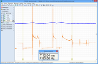
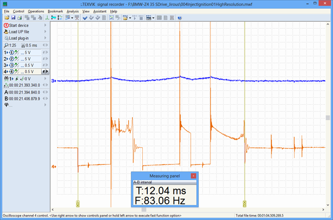
The mixture is ignited by 3 sparks with a duration of 12 ms ! (7107/8)
There are 3 ignition signals at the TDC position and they do not change in anyway and don't appear to be deffective at higher loads or during rapid accelerations.Workplace for 20 minute test drive recordings (7107/9)
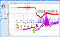
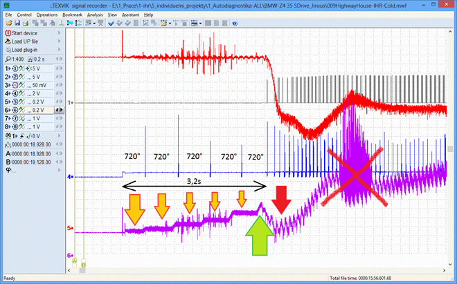
The misfires at about 80-85% engine loads can be invoked only during test drives. This mode was determined by repeated test drives with a connected 8-channel data recorder TEXVIK DS.Long cranking - up to 10 engine revolutions before the engine starts (7107/10)
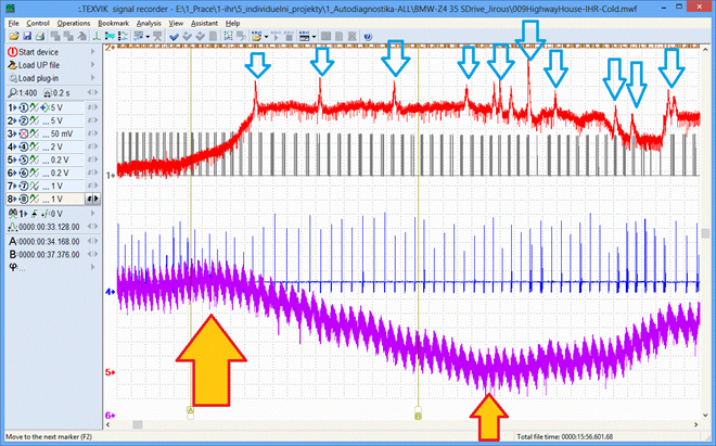
Red = MAP sensorGrey = cylinder #2 fuel injector
Blue = cylinder #2 ignition signal
Purple = high fuel pressure (all on the component side)
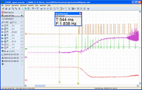
The engine ECU is not controlling the fuel injectors until the rail fuel pressure increases. The fuel pressure is rising very slowly and in steps (yellow arrows). Once the rail fuel pressures reaches the required value (green arrow) the ECU activates fuel injection and the engine starts (after about 3,2 seconds and up to 10 engine revolutions).
Do not pay attention to the red crossed out trace. This is just noise from some strong electromotive module and has nothing to do with the fault.
Rail pressure collapses after 14 seconds (7107/11)
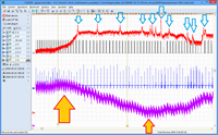
Red = MAP sensorGrey = cylinder #2 fuel injector
Blue = cylinder #2 ignition signal
Purple = high fuel pressure (all on the component side)
About 14 seconds after the cold engine started the engine begins to fire into the intake (blue arrows). This is the result of the collapsing fuel pressure while the engine is running (large yellow arrow) all the way to the lowest values (small yellow arrow).
The engine at his moment has problems and when it is about to stall rail fuel pressure is restored and the engine improves its running performance without firing into intake.
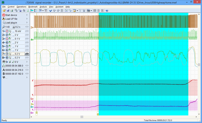
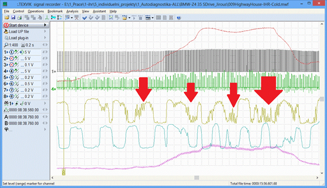
Problem no. 3 – detail of oxygen shocks in the 80% engine load zone (7107/12)
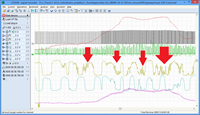
Red = MAP sensorKhaki and bluegreen = Upstream Lambda sensors
The red arrows are pointing to incomplete mixture combustion in the cylinder at a specific accelerator pedal position under load when the engine is not performing smoothly and is loosing some power. Even though there is no low rail fuel pressure (we don't know what the value should be) the engine is lacking fuel and one of the cylinders is misfiring due to bad combustionability.
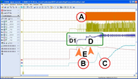
High fuel pressure pump defect proof (7107/13)
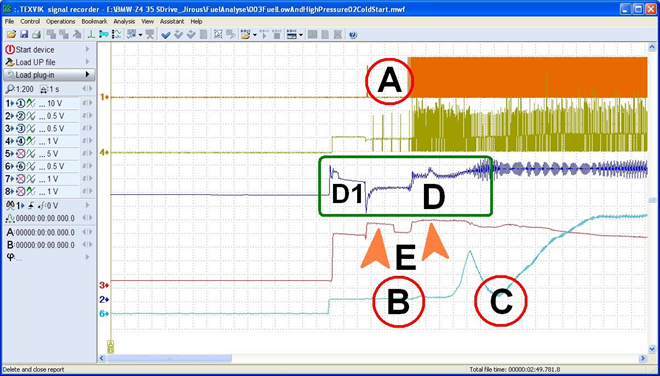
Channel designations:From top down:
Ch1: Orange = cylinder #2 fuel injector
Ch4: Khaki = cylinder #2 ignition signal
Ch2: Blue = low fuel supply pressure
Ch3: Red = el. current of high pressure pump fuel quantity solenoid
Ch6: Light blue = rail pressure sensor signal
Recording: Cold start
Recording description:
A = During complete 8 engine revolutions the fuel injectors are not injecting
B = Even though the fuel pump is turning it doesn't have sufficient pressure
C = Shortly after the engine starts the fuel pressure drops for a while
D = Low fuel pressure value of the delivery pump is OK
D1 = System is pressurized after the ignition is switched On
E = The engine ECU is trying to control the fuel quantity solenoid to achieve higher pressure but the pressure is not increasing. Mechanical defect of the high pressure pump.
Misleading.. (7107/14)
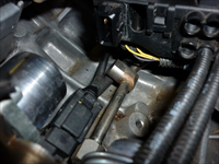
The Freeze Frame data is pointing towards missing high fuel pressure and misleading is that there is reference to a value from a low fuel pressure sensor in the fuel circuit. The vehicle has no low fuel pressure sensor and there is no hole in the original bracket. The engine ECU doesn't have this information and has no wire installed in the connector for the low fuel pressure. The pressure value 0,00 hPa in low pressure circuit shown by the diagnostic software is misleading in this case.Connected to the fuel quantity valve in the junction box (7107/15)
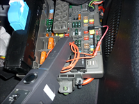
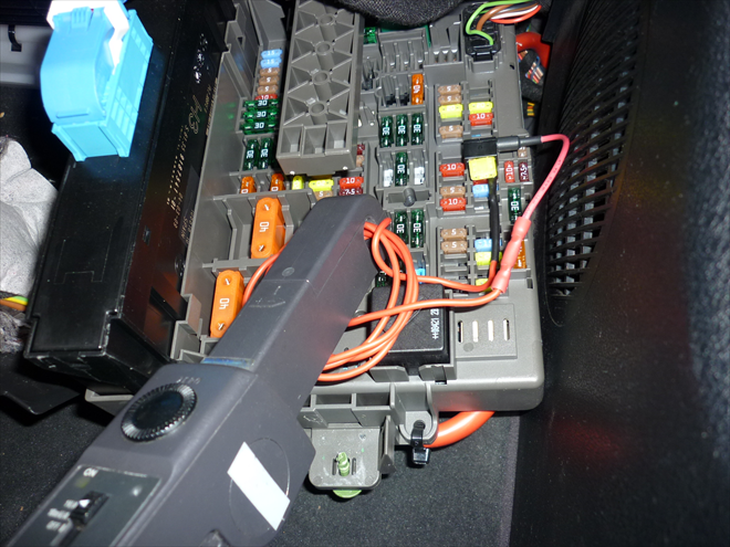
The best method how to measure the dynamics of the control current of the fuel quantity solenoid is to install a wire adapter for the mini fuse in the junction box and attach current clamps to the wire adapter.Pressure transducer HD 26A (1 V = 1 bar) (7107/16)
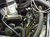
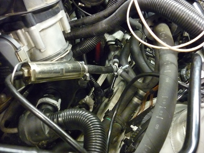
If this model saved money by not installing a low fuel pressure sensor we have to measure the pressure with our own sensor.Information about air bubbles in the fuel system is quite useful (7107/17)
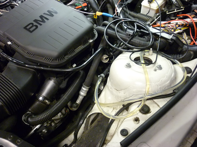
It is useful to know if there are air bubbles in the fuel system. On direct injection systems without a return line the air bubbles have no choice but to enter the engine and thus the engine can jerk. No air bubbles on our engine.CAUTION!
Not all clear hoses will withstand petrol and may break in a couple of minutes.
Warning for all modern BMW vehicles (7107/18)
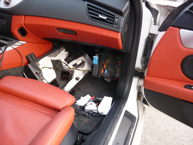
If you start working on the vehicles electrical system it is common with BMW that vehicles electrical system wakes up unexpectedly twice after about 5 minutes and after about 20 minutes without the ignition key in the ignition switch. This is preprogrammed by the manufacturer and cannot be influenced in anyway.Best is to start working on the vehicle after 1/2 hour when all the ECUs go to sleep or to disconnect the battery.
DANGER 1: If electronic components or modules are being disconnected when the vehicle unexpectedly wakes up, then such components can be permanently damaged.
DANGER 2: If the fuel circuit is disconnected and the vehicle unexpectedly wakes up high pressure fuel can squirt out and cause serious injuries.
Verification (7107/19)
Testing the fuel quantity solenoid with the Activator Testeru shows that when the solenoid is activated by an external current source the solenoid is working correctly but the mechnical part of the high pressure pump intermittently is not capable of delivering the required high pressure.Good engine start with defective pump... (7107/20)
Channel designation:Ch2: Brown = cylinder #2 fuel injector
Ch4: Green = cylinder #2 ignition signal
Ch6: Purple = rail fuel pressure
Ch5: Red = MAP sensor
Recording: Semi-hot engine start
Description: If the engine is not left to soak for longer than 2-3 hours the engine restarts within 1/2 second..
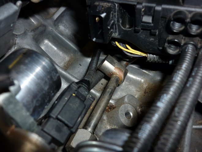
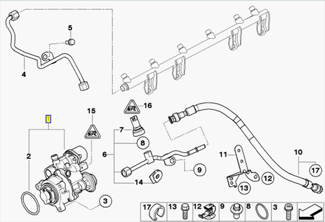
The vehicle VIN based documentation is showing a low fuel pressure sensor - not on vehicle (7107/21)
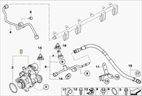
Position no. 7 is indicating that the vehicle should be equipped with a low fuel pressure sensor. No sensor on the actual vehicle (see photo 14).FCD note: BMW interactive parts catalogue is pointing out this possibility.
Problem of "dry" valves on direct injection engines: contaminated intake valve stems (7107/22)
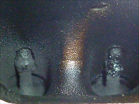
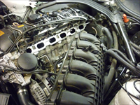
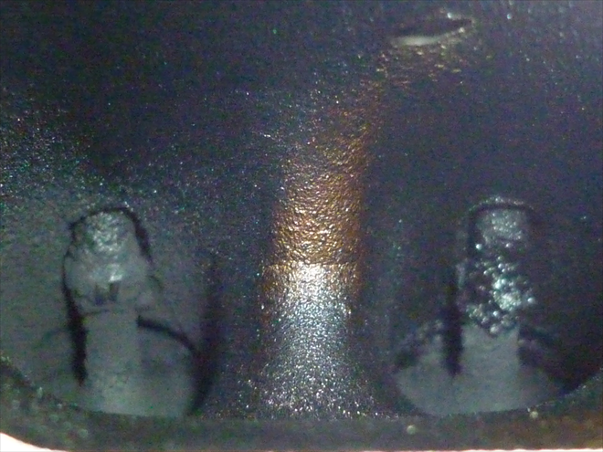
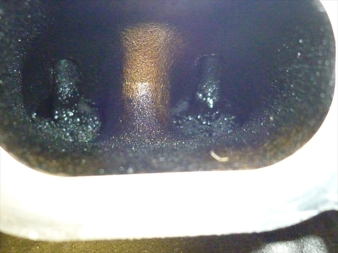
I was prepared to remove the high pressure pump and this required removal of the intake. The intake inspection revealed a strongly contaminated intake, the valve stem are covered with condensation deposits. The worst is valve on cylinder #6 a is better towards valve on cylinder #1. Laminar flow through smooth intake channels is not possible in this condition of the intake system.The air cleaner filter hasn't been replaced for a long time. It is very dirty.
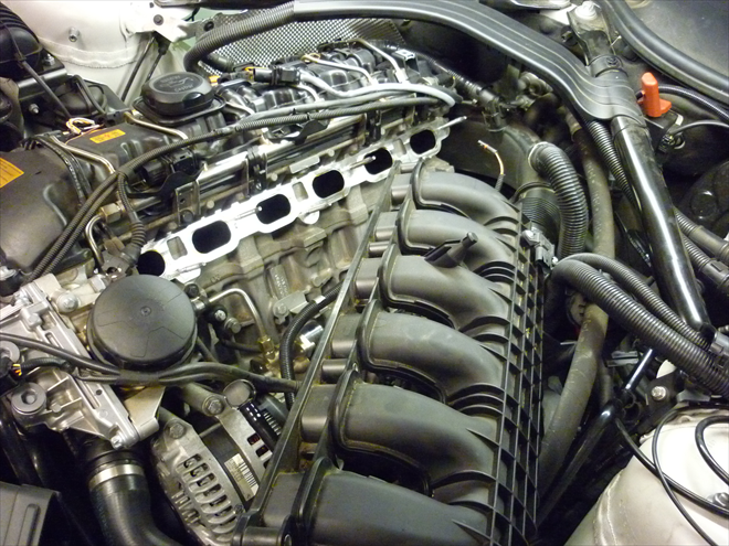
Intake system discovery (7107/23)
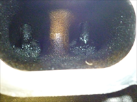
Starting from cylinder #1 that is reasonably clean the contamination level gets worse towards cylinder no. 6. This is an indication that the rear cylinder bank recieves the oxygen shocks sooner than bank 1 in the front.Cylinder #6 (7107/24)
Contamination of cylinder #6 is very high.Cylinder #5 (7107/25)
The most contaminated cylinders are cylinders #4, #5 and #6. This may be related to the fact that crankcase ventilation outlet is above these cylinders.Difference between the defective.... (7107/26)
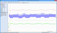
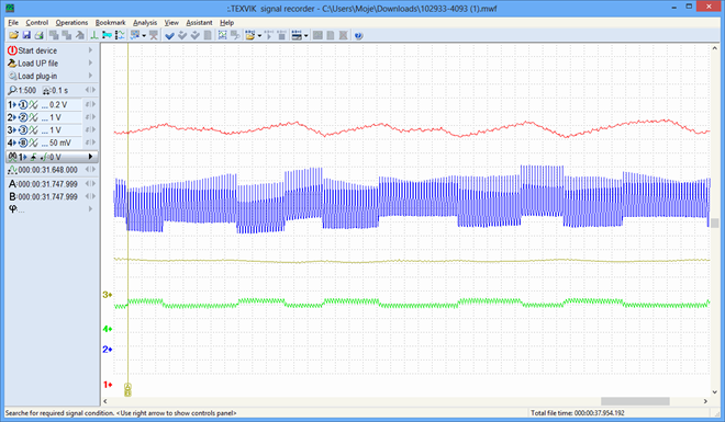
Channel designation:Ch1: Red = rail high fuel pressure
Ch2: Blue = fuel quantity solenoid on the high pressure pump
Ch3: Greygreen = low fuel pressure
Ch4: Green = fuel quantity solenoid el. current
Recording: at idle
Description: fluctuating regulation
With new high pressure pump (sent by Frank Schäfer - FCD Deutschland) (7107/27)
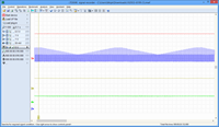
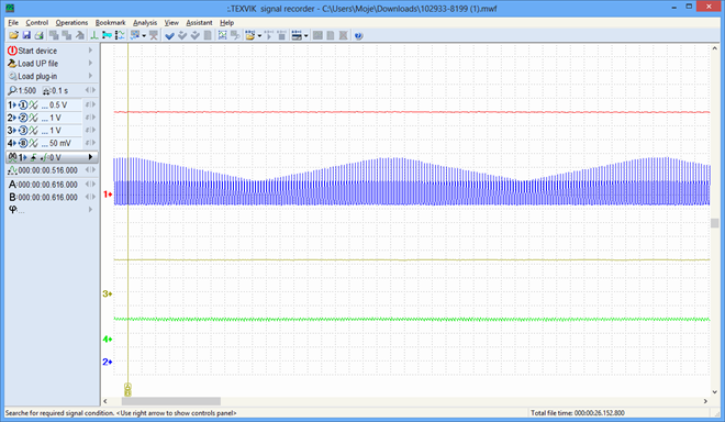
Channel designation:Ch1: Red = rail high fuel pressure
Ch2: Blue = fuel quantity solenoid on the high pressure pump
Ch3: Greygreen = low fuel pressure
Ch4: Green = fuel quantity solenoid el. current
Recording: at idle
Recording description: Regulation is stable and doesn't fluctuate





Komentáře (0)