
Akademie
- 2. blok - Diagnostic methods
- Parallel diagnostics (počet lekcí: 0)
Electricity – similarities with water @


Obsah článku:
Úvod
BAD HABITS:
HOTLINE telephone call: Reply to a question how the fuel pump was tested: "We have verified that the fuel pump is OK, it has power supply...", These kind of similar sentences have forced me to prepare a simple test manual of how to measure the correct electrical values and to compare electrical behaviour with water behaviour (see video - Waterflow Car Diagnostics).
GOOD HABITS:
When you are watering the garden, water pressure on its own is not enough, you also need water current! "VOLTAGE" is not an important indicator (a secondary indicator) when evaluating Work performed by consumers. The main information from any consumer (throttle valve, turbocharger, ignition, fuel pump, xenon lights, all kinds of regulators..) is "CURRENT" or to be more specific its dynamic waveform in graphic form (this is only possible with an oscilloscope).
FOR REFERENCE
For your reference you can use an applet on the following page and simulate the dynamic behaviour of components in an electric circuit: http://www.falstad.com/circuit/
(ALL ELECTRIC/ELECTRONIC SCHOOLS SHOULD USE THIS INFO)
HOW TO MEASURE CURRENT AND VOLTAGE
On consumers we always measure current (always with an oscilloscope)!
Readings are obtained by a contactless measurement where one of the wires is surounded by current clamps. It doesn't matter if the positive or negative side because the same current that is flowing in must flow out. You can't damage the vehicle in anyway.
The only exception when to measure voltage on consumers is for supplementary reasons when the current development trace is not correct. In such cases we are interested if the power supply and ground path are OK.
If it is a sensor or communication line we always measure voltage (always with an oscilloscope)!
We are going to connect to power supply terminals. With this, we have to explain the reasons where and why we have to connect to this position. If we are going to use an highohm oscilloscope (with inernal resistance of about 1 MOhm and higher), than there is nothing that we can damage on a car! We must observe all rules related to work safety in conjuction with dangerous voltages.
Can an oscilloscope find worn hydraulic lifters?
YES, it can!
The oscilloscope only measures and displays electrical signals, but it is possible to monitor and evaluate almost everything. Battery discharge, cylinder head gasket damage, worn out dual-mass flywheel, clogged injector holes or a leaking fuel return valve.

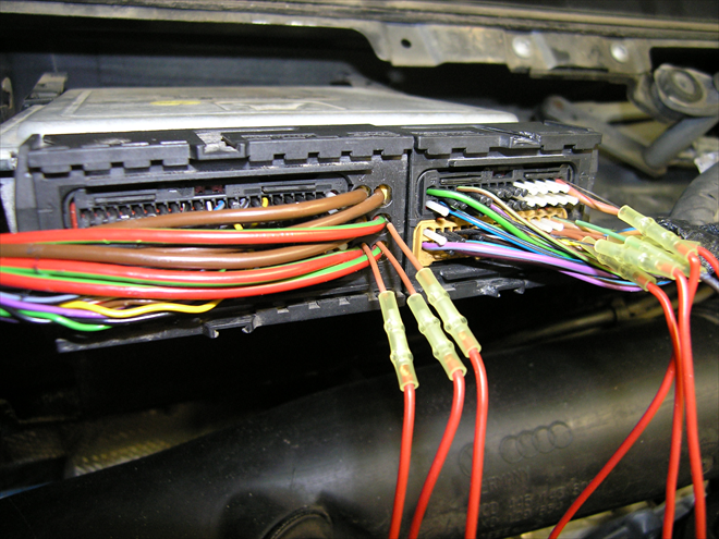
Connecting without danger of damage (1841/1)
It doesn't matter where you place the probe, if you know that the test equipment has internal resistance of about 1 MOhm or higher (all automotive digital multimeters and oscilloscopes have).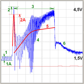
Are we measuring only voltage? Then here (airflow sensor) we are measuring correctly (1841/2)
On sensors we measure voltage and not current!Petrol, normal aspirated engine with a throttle valve controlled by wire.
Blue = airflow sensor signal
1-1A = idle (relative balance evaluation of individual cylinder intake capabilities; average voltage at idle)
2 = intake "aspiration" (the peak is showing the maximum sensor possibilities = the quickest airflow, where a value of about 4.2 V is expected. This applies to almost all voltage type airflow sensors)
2A = red trace = "worn" (contaminated) heated foil
3 = engine cranking
4 = air resonance caused by individual cylinder air intake (here we would see intake system "backfire", if it was present).
5 = this is how the trace shape would look like if the exhaust system is restricted (partially restricted).
6 = idle control intervention with throttle valve (evidence that the control is operating)
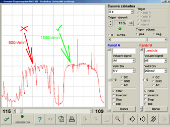
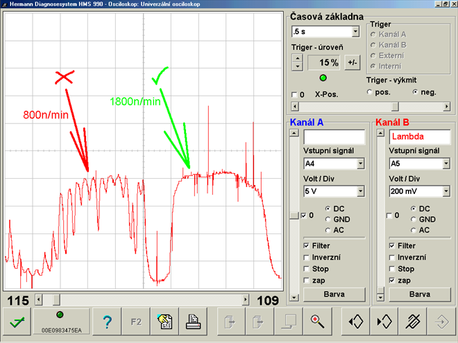
Measuring voltage is sufficient (sensor) - lambda sensor signal analysis at idle and increased idle (1841/4)
Spark plug or fuel injector? On the left lambda sensor signal we can see at idle oxygen shocks (unburnt oxygen from one of the cylinders on a 4-cylinder engine). At higher rpm (right) the shocks disappear. This is how 90% of injector valves behave. In some rare instances this could be also caused by seizing cylinder head valves in their valve guides.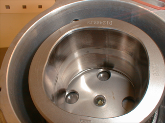
This badly worn high pressure pump (Delphi) was revealed by an oscilloscope (1841/5)
An oscilloscope, better a signal recorder (oscilloscope with continuous recording to PCs HD) can reveal a damaged high pressure pump with a few easy tests. The important condition for this is that the test results of a suspected pump have to be compared with measurements of a good pump. These reference traces can be found for most applications on our web portal.
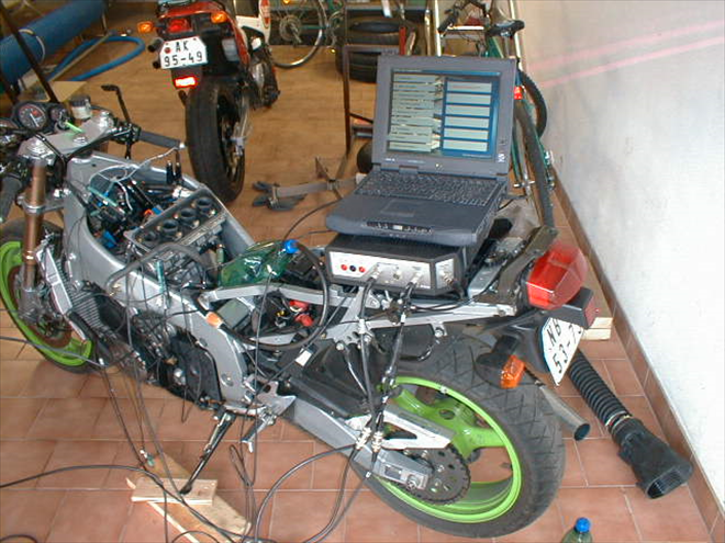
Even carburetors can be tuned more correctly with an oscilloscope, than using vacuum (1841/6)
Because motorcycles with carburetors do not regulate ignition timing for each cylinder independently. By measuring the time difference between each cylinder ignition it is possible to determine which cylinder is slower. To compensate (adjust) the timing difference all we need to do is to open the throttle valve so that engine runs smoothly. The time difference of the individual cylinder ignitions on the oscilloscope time-base must be the same.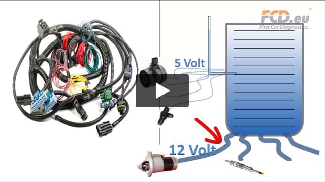
Waterflow Car Diagnostics – How to measure Voltage and Currrent (1841/7)
Basic course for car technicians, to help them remember basic rules during fault analysis – How and Why to measure.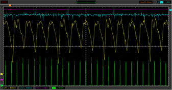
The oscilloscope has revealed an internally damaged valve lifter on a TDi engine (1841/9)
Airflow sensor attached unconventionally on the intake manifold (bypassing the turbocharger and intercooler) can reveal even issues that we cannot detect by a thorough visual inspection. This is how a worn valve lifter behaves by not allowing sufficient cylinder flushing on cylinder no. 4 of a 1.9 TDi engine from the year 2000 (330 000 km)
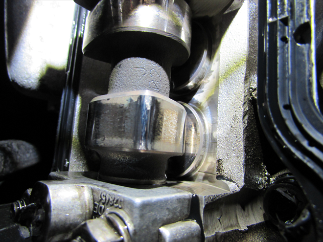
Internally damaged valve lifter – outside no damage (1841/10)
The oscilloscope has revealed on one valve lifter (cyl. no. 4) too much wear on the inside of the valve lifter. On the outside there are no signs of damage. The inlet process of each individual cylinder will only show on a dynamic recording of intake cycle pulsations of individual cylinders.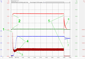
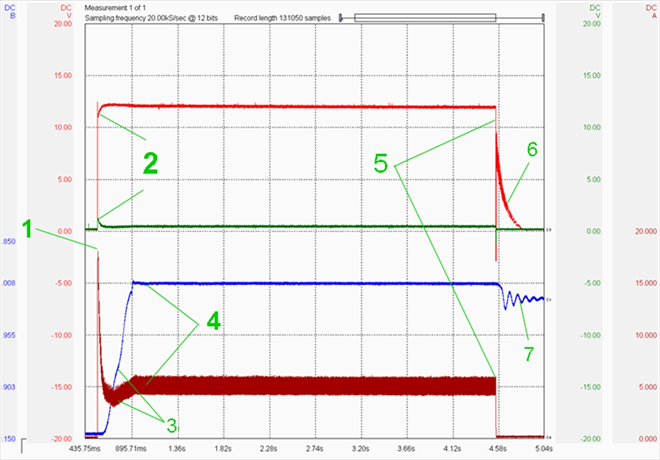
Consumer = must test current (1x turn of the ignition key = 7 tested parameters) (1841/11)
The fuel pump is an "electric machine" generating work. The main value for all electrical consumers is CURRENT! The secondary value is the voltage development trace. When recorded in dynamic mode, we can read a lot of other information!1 = Current peak (current when pump starts moving) = Evidence that we do not need to look in the fuel pump circuit for any contact resistance! A circuit that can flow 15 A at peak load 15 A doesn't have any contact resistance.
2 = Power supply and ground have almost no voltage drop. Another confirmation that everything is OK.
3 = The pump current at the start phase drops slightly, but then it rises slightly and remains stable. Evidence that there is no fuel loss and that the pump has started moving as it should.
4 = Fuel pressure at start – very short phase for reaching max.required pressure – OK.
5 = Fuel pump OFF stage
6 = The fuel pumps inertia is showing that the pump is moving freely.
7 = The fuel pressure pulsations are showing that the fuel pressure regulator is working correctly and is keeping the fuel pressure at the bottom control threshold.


Komentáře (0)